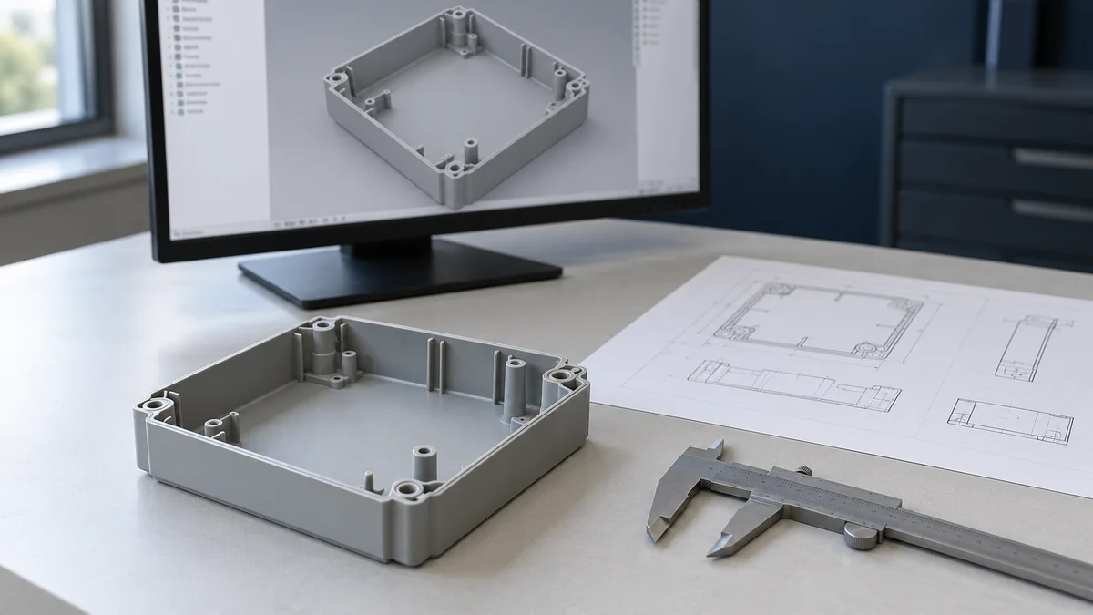
A design for manufacturing review connects the intended part function with the practical requirements of molding and tool construction. It works best before the mold design is released, while decisions about surfaces, interfaces and geometry are still manageable. The output should be a documented set of decisions, rather than a collection of comments disconnected from the drawing revision.
Use these ten checks to prepare that conversation. The appropriate dimensions and process limits depend on the resin, part geometry and molding arrangement. This checklist deliberately avoids universal wall thicknesses, draft angles or tolerance promises.
1. Confirm the resin and design revision
Identify the complete resin grade, reinforcement, color and applicable material requirements. Keep the 3D model, 2D drawing and specification on the same revision. Record which file controls dimensions and which controls geometry if a conflict appears. A review based on an obsolete drawing can resolve the wrong problem very thoroughly.
Include the intended use conditions and any material substitution rules. The resin producer’s processing guidance is a starting point for the tooling discussion; it does not automatically validate the finished design. Changes to grade or filler may require another review of shrinkage, gating and surface expectations.
2. Look for abrupt wall changes
Examine sections through corners, intersections and concealed geometry. Thick local regions can cool differently from surrounding walls, creating a risk of sink, voids or distortion. Thin regions may be difficult to fill depending on flow length and material behavior. Review transitions in the context of the selected resin.
Coring out unnecessary mass can help, but the change must preserve function and leave a moldable geometry. Eastman’s processing and mold design guidelines discuss these relationships for its materials. Treat such guidance as material-specific input rather than a universal numerical rule.
3. Check ribs, bosses and intersections
A rib can add stiffness without making the entire wall thicker. Its base, height, draft and connection to the surrounding part still require attention. Intersecting ribs or a boss joined directly to a cosmetic wall can create local mass that is easy to miss in an external view.
Review fastener loads, alignment and assembly access together with moldability. Protolabs’ plastic boss design reference explains why boss geometry depends on function. Identify where a sink mark would be unacceptable and discuss alternatives before the tool layout constrains the options.
4. Define the draw direction and draft
Establish the mold opening direction, then examine surfaces that must release along it. Deep walls, ribs and textured faces need specific attention. Draft affects part geometry and mating clearances, so it should be incorporated into the model rather than left as an unspecified adjustment for the toolmaker.
The required angle depends on surface treatment, depth, material and the ejection arrangement. Protolabs’ draft guidance illustrates the importance of deciding this early. Agree which dimensions are measured at the top, base or another defined plane after draft is applied.
5. Identify undercuts and parting lines
Locate holes, clips, recesses and other features that prevent a straight release. Some features may be handled through a different parting line or shutoff arrangement; others may require moving mold elements or a part redesign. These choices affect complexity, access and maintenance.
Mark acceptable parting line locations on visible and functional surfaces. Include any limits on witness marks or flash in the acceptance discussion. Protolabs’ side-action overview is a useful illustration of geometry-dependent options, rather than a guarantee that every undercut can be handled in the same way.
6. Review gates, flow paths and weld lines
Identify permitted and prohibited gate areas. Consider how melt must travel around openings and whether meeting flow fronts could create a cosmetic or functional concern. A gate location that looks convenient for tool construction may be unsuitable for a visible face or a heavily loaded feature.
Discuss where flow analysis would be useful and what assumptions it would use. Exact resin data, geometry and processing conditions affect the result. BASF’s injection molding troubleshooter treats molding defects as problems with interacting material, process and design causes; one drawing change does not resolve every possible cause.
7. Specify venting and cooling considerations
Review likely end-of-fill locations, deep pockets and areas where air could become trapped. Vent details must suit the resin and tool arrangement. Avoid prescribing a generic vent depth without material and process context.
Also identify hot spots and restricted areas for cooling. Cooling channels compete with inserts, screws, ejectors and moving elements for space. Raise these conflicts during layout review. A tool can be geometrically manufacturable while still presenting difficult thermal behavior in production.
8. Agree ejection and handling surfaces
Identify where ejector marks are acceptable and whether the part has enough support during release. Thin walls, flexible clips and cosmetic surfaces need careful review. Discuss whether the part remains on the intended mold half and how it is removed without damaging functional features.
Include downstream handling. A part that ejects successfully may still be difficult to orient, separate from a runner or place into an assembly fixture. Document any robot access or manual handling requirements supplied by the receiving molding team.
9. Distinguish critical dimensions from general tolerances
Mark the features that control fit and function, with defined datums and measurement conditions. Avoid assigning the tightest available tolerance to every dimension. Resin shrinkage, fiber orientation, cooling and conditioning influence the molded part, so dimensional requirements need evaluation against the actual design and material.
Agree the inspection method and sample condition for each critical feature. A flexible housing measured unsupported can give a different result from one constrained in an assembly. This is an acceptance question to settle before tooling, rather than an argument to postpone until samples arrive.
10. Close the review with recorded decisions
Create an action list with drawing references, owners and approval status. Distinguish accepted changes, open questions and assumptions requiring trial confirmation. Update the controlling files after approval and retain the revision history.
Before releasing the mold design, confirm that the receiving machine specifications, target schedule and agreed acceptance criteria are included in the project record. A DFM review reduces avoidable ambiguity; it does not remove the need for sampling, process development and a project-specific acceptance decision.
Sources and further reading
Use the selected material producer’s current guidance and project-specific engineering review alongside these references.